NebulaTor
A CN3D-designed upgrade for the BIQU/BTT Nebula Extruder, developed around improved filament handling, sensing, serviceability, and an integrated cutter system.
Files coming soon: documentation is public now, STL files are planned next, and CAD/STEP files will follow only after final validation.
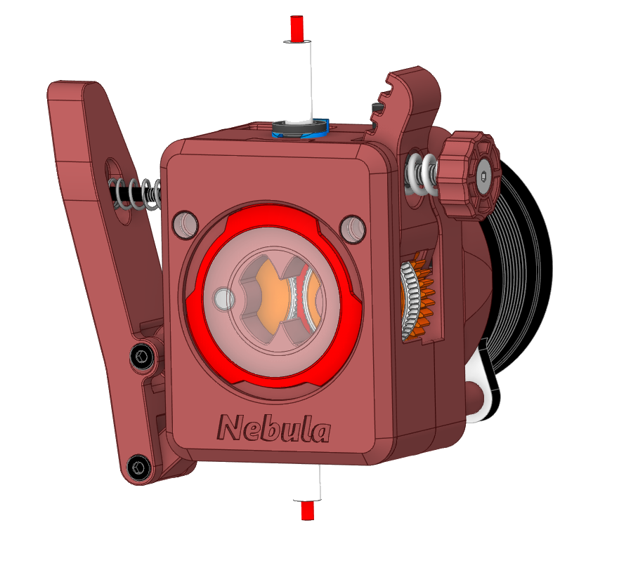
Assembly Preview
This page follows the verified sequence in the current project manual. It is useful for understanding the build flow, but the fully validated assembly guide will accompany the STL release.
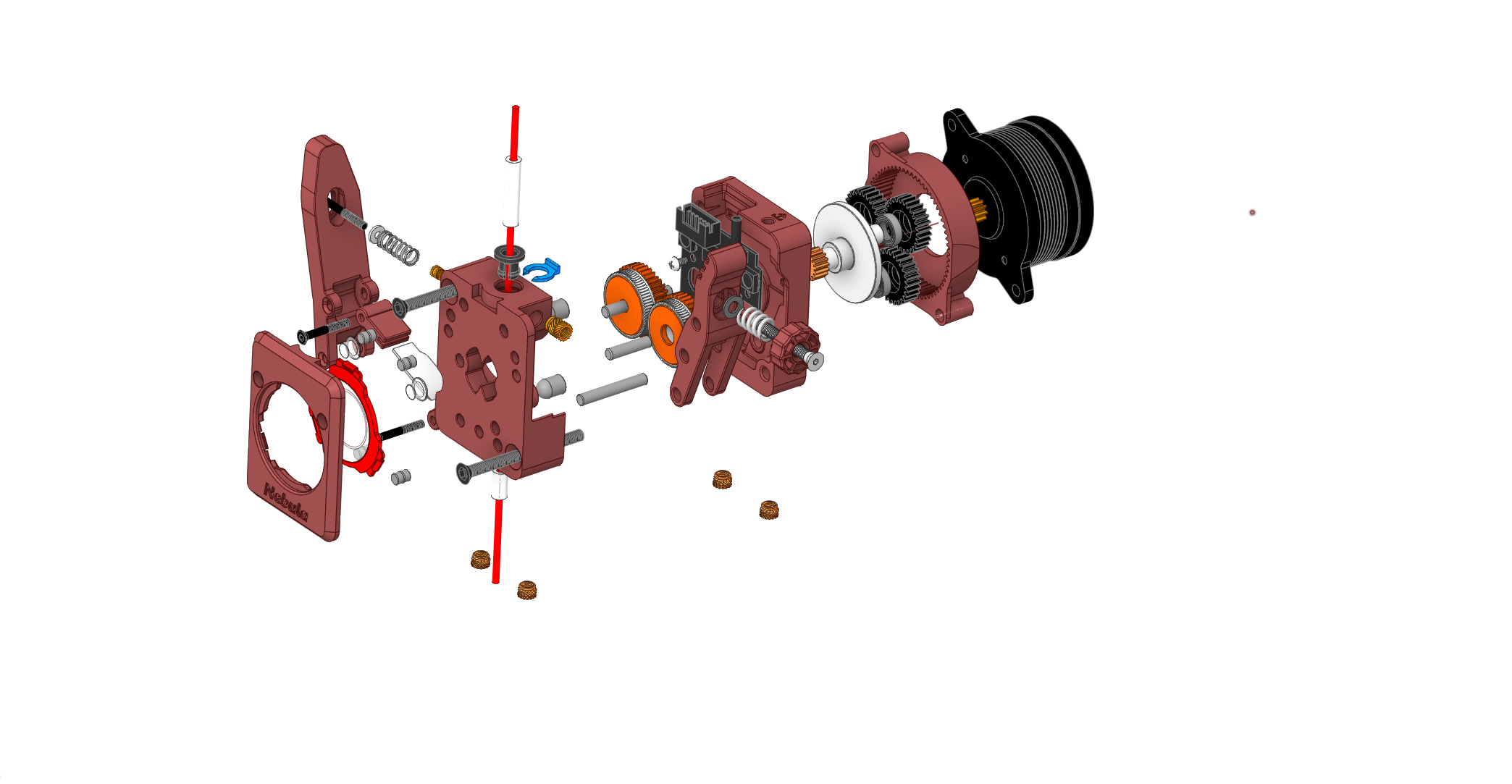
Preparation
- Print parts in a suitable material such as ABS, ASA, or PETG. ABS is the recommended final project material.
- Heat-set the documented brass inserts.
- Deburr the filament path and PTFE bores.
- Confirm smooth filament feed before final tightening.
Assembly sequence
Prepare inserts and filament path
Install heat-set inserts, clean the filament path, and prepare inlet and outlet PTFE areas.
Install PTFE path
Insert the top inlet PTFE and short outlet PTFE, then secure the inlet collet with the blue C-clip.
Assemble the idler lever
Assemble the lever pivot, spring, and tensioner knob, then attach the lever to the body and verify smooth travel.
Install the drive train
Install hobbed gears on their shafts, align the hobs with the filament plane, and verify smooth rotation.
Mount motor and gear stage
Mount the motor and gearbox, mesh gears without binding, and tighten screws evenly.
Join the main body
Mate the motor plate and main body, tighten screws diagonally, and rotate the motor shaft by hand to confirm smooth motion.
Fit front cover and window
Install the accent ring and window, then attach the front cover.
Set spring preload
Insert filament and tighten the tensioner until filament does not slip. The manual suggests starting around one to two preload turns.
Electrical and motion checks
Connect motor and sensors, test manual filament feed, and run a slow extrude test.
Firmware calibration
Verify rotation distance and steps/mm, then tune Pressure Advance or Linear Advance for the user firmware environment.
Final Mechanical Checks
- No rough movement through the filament path.
- No gear binding when rotating by hand.
- No slipping after initial spring preload.
- No grinding marks from excessive preload.
- Sensors and switches respond before printing.