MMX
Um caminho completo do zero até uma configuração Klipper multicolor funcional: arquivos, BOM, montagem de hardware, fiação, configuração Happy Hare, calibração, primeira impressão e suporte.
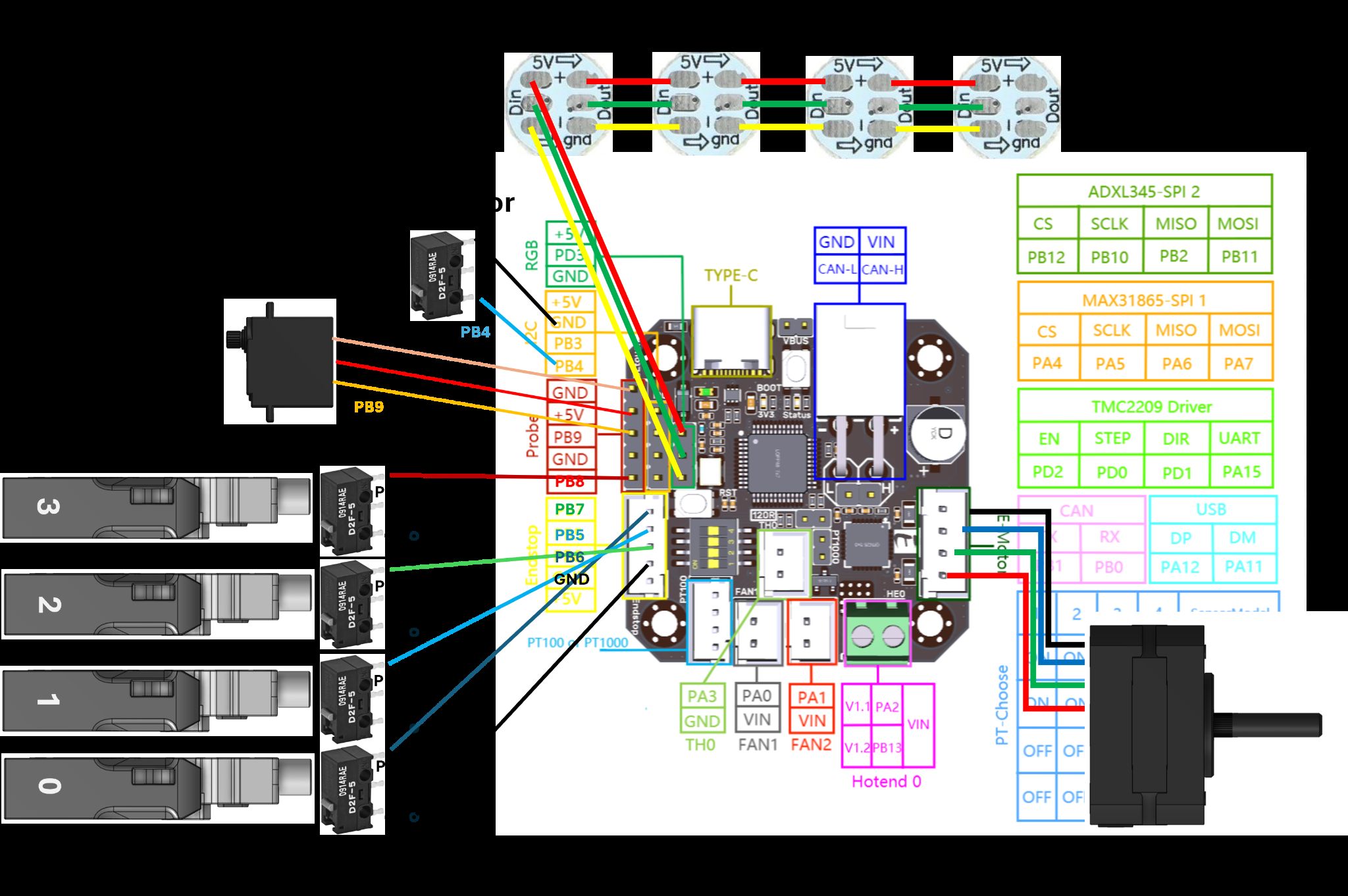
EBB42 wiring overview
The MMX reference build uses the BTT EBB42 as its main control board. The diagram below shows the full pinout as documented in the MMX wiring guide. If your board differs, use your actual pins and update Happy Hare aliases accordingly.
Adding a Step-Down Converter
Use a step-down converter to power the MMX 5V rail and servo from the printer's 24V supply. Connect 24V+ to IN+ and GND to IN-, then adjust the converter output to approximately 5.1V before connecting it to the MMX.
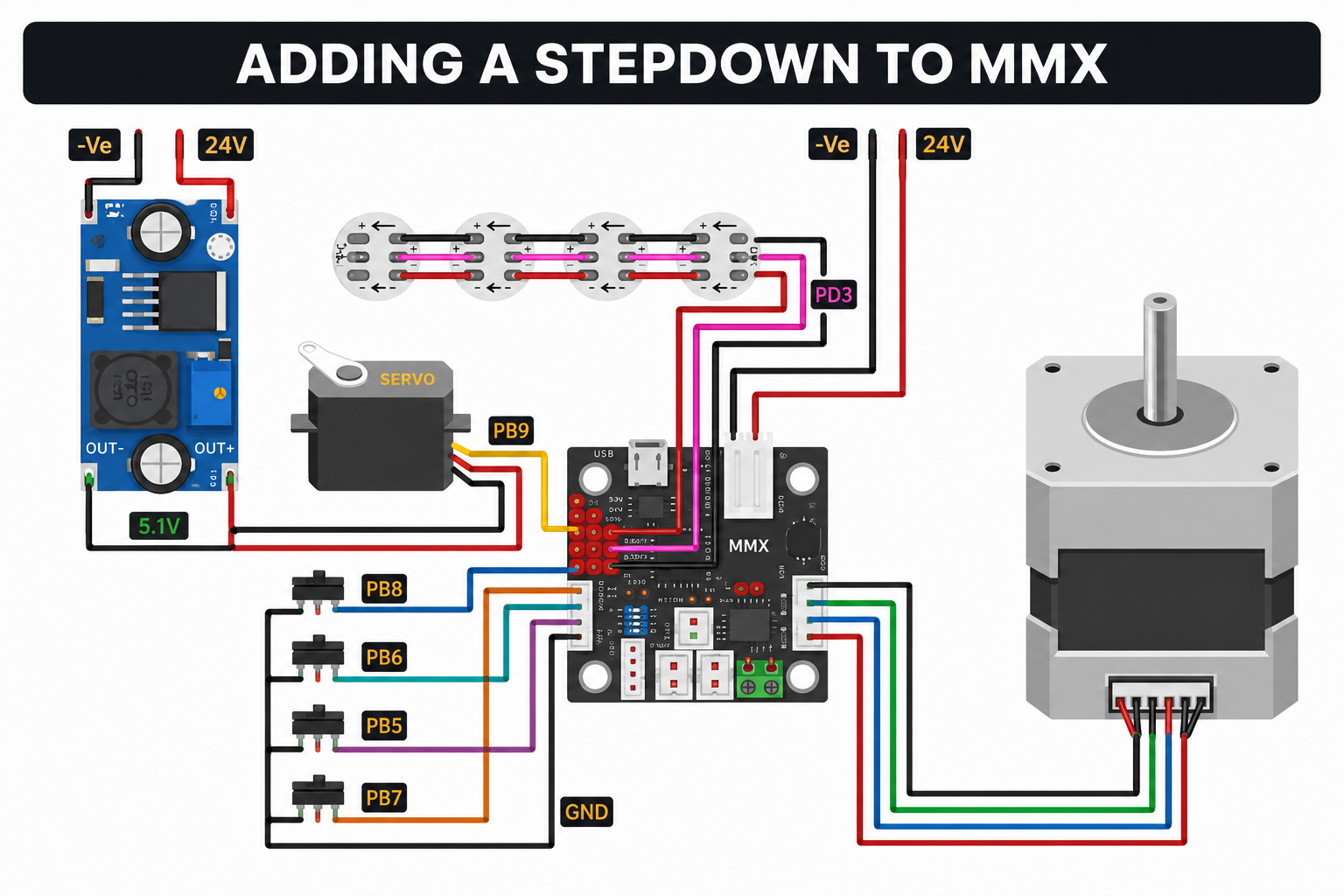
- OUT+ supplies the MMX and servo 5V rail.
- OUT- connects to MMX GND.
- The servo is powered from the regulated 5.1V output.
- All grounds - printer PSU, MMX board, controller and step-down converter - must share a common ground.
- The remaining MMX wiring stays exactly as shown in the diagram.
- Never connect 24V directly to the MMX 5V rail or the servo.
- Measure the converter output with a multimeter and adjust it to approximately 5.1V.
- Double-check polarity before powering the printer.
- Perform all wiring with the printer powered off.
Internal components reference
Identify the main hardware inside the MMX enclosure before routing wires. The EBB42 board mounts on the sled; the stepper and servo mount on the rear plate.
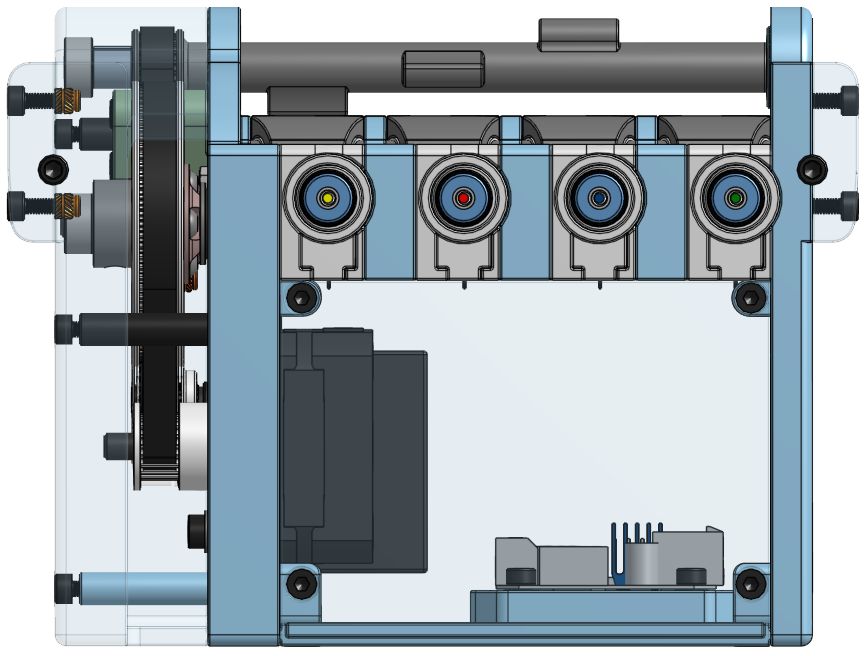
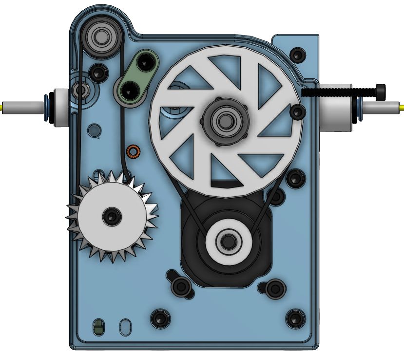
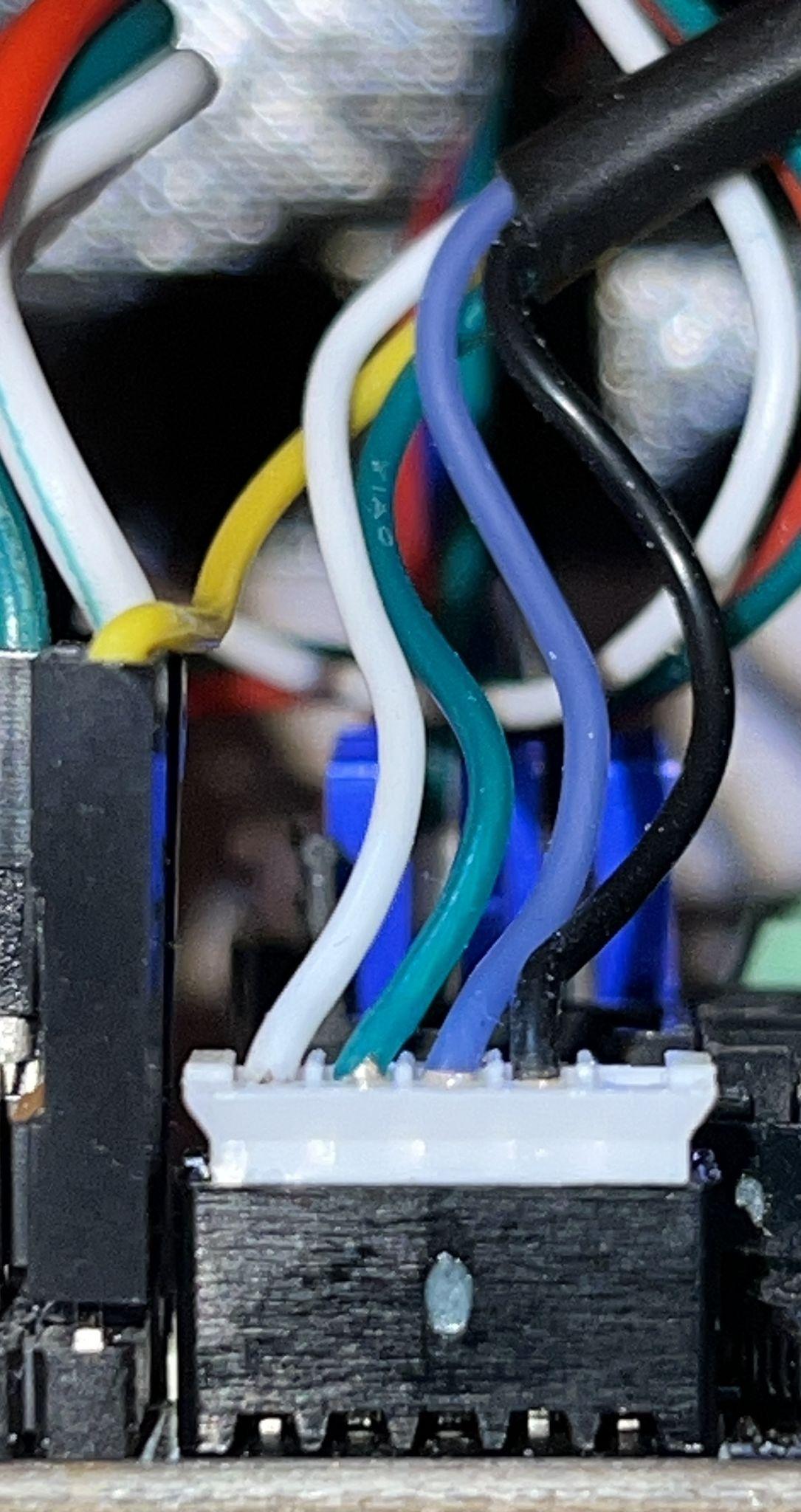
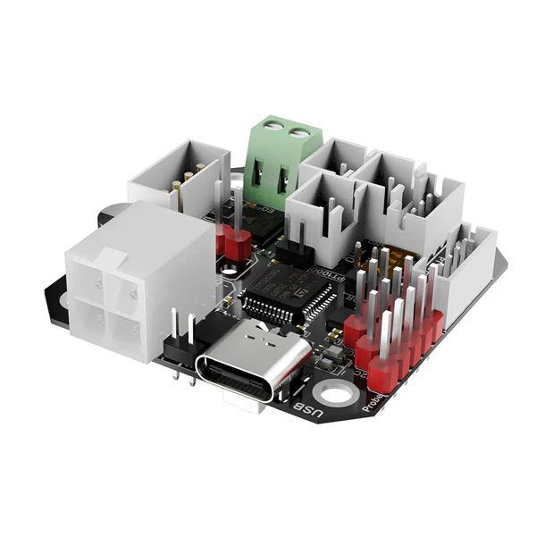
Gate switch harness and EBB42 board layout
Each pre-gate sensor connects to the EBB42 via its own switch harness. The board render shows physical connector locations to help route each harness to the correct header.
EBB42 pinout
Reference pinout from the MMX wiring diagram. If your board or wiring differs, use your actual pins and update Happy Hare aliases accordingly.
| Function | Pin | Use |
|---|---|---|
| Gate 0 pre-gate switch | PB7 | Filament detection |
| Gate 1 pre-gate switch | PB5 | Filament detection |
| Gate 2 pre-gate switch | PB6 | Filament detection |
| Gate 3 pre-gate switch | PB8 | Filament detection |
| Selector servo | PB9 | Selector/camshaft movement |
| RGB / NeoPixel | PD3 | Gate LEDs |
| Stepper UART | PA15 | Gear stepper control |
| Stepper STEP | PD0 | Gear stepper control |
| Stepper DIR | PD1 | Gear stepper control |
| Stepper ENABLE | PD2 | Gear stepper control |
| Toolhead sensor | PB4 | Toolhead filament detection |